A brief approach

In general, rock mass can be defined as a single rock material or a set of rock masses composed of one or more lithological types, located in situ, with water presence, pre-existent stress states, being intercepted or not by discontinuities separating the solid material into blocks of rocks.
Geological discontinuity is a general term referring to any geological entity that intersects the physical continuity of a given rock mass, thus refers to any mechanical break within rock masses, such as faults, fractures, cracks, joints, fissures, diaclases, weakness planes, bedding planes, cleavage, foliation, schistosity, shear zones etc ISRM, 1978 cited in Shang et al., 2018; BSG).
Joints are the widely used term in mining engineering context to describe the totality or part of discontinuity set, especially when calculating rock factor – resistance to blasting – to predict fragmentation results/size in blasting operations.
It is worth mentioning that discontinuities system can be observed since microscopic (textural characteristics) to macroscopic level – pre-existents by geological action and those induced by secondary actions of previous detonations.
It is known that huge geological heterogeneity and local variation of rock masses are consequences of the numerous processes that occurred throughout geotectonic history, lithology of the rocks that constitute them, their degree of fracturing and degree of alteration. Each rock mass presents distinct particulates which will consequently reflect in some manner on its behavior during rock blasting process. Several characterization systems were proposed over the years for estimation purposes in relation to its quality, drilability, scavability, breakability, fracturability, explodability, blastability, stability classification of rock mass and others. In practice, estimating the capability of rock mass to be detonated and consequently the three-dimensional (3D) distribution of this capability is a challenge, but it is necessary to then elaborate a specific blast design according to the rock mass properties to attain fragmentation control. Therefore, it´s essential that, in a preliminary stage, a rock mass characterization is made in order to understand the explosive-intact rock interaction to predict resistance of the rock material to detonation.
In accordance with illustrated in the Fig. 3, we can say that rock fragmentation distribution, and consequently control of the operation is directly related to internal factors that govern a specific in situ rock mass (uncontrollable factors) on one side, and external factors associated with blast design parameters (controllable factors) on the other.
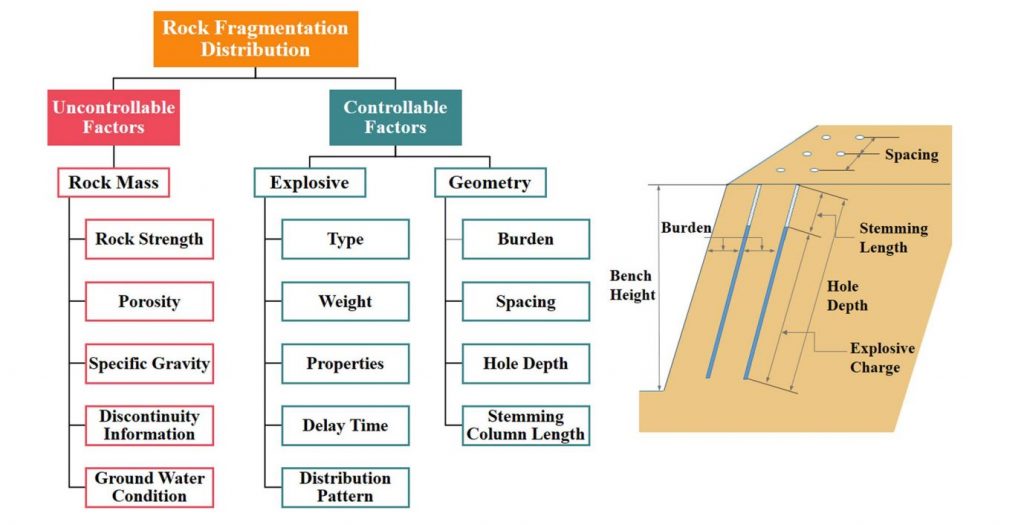
Summing up, uncontrollable factors include rock strength (Uniaxial Compressive Strength, UCS), porosity, density, fracturing information, ground water condition, deformation (Young’s Modulus and Poisson’s ratio) and alsostability characteristics (cohesion and friction angle) (Zhao et al. 2018; Aydan et al. 2014 in Navarro et al., 2021). These can be attributed as one of the most used parameters for the rock mass characterization and relevant for blasting with explosives. In terms of discontinuity information, it is relevant to obtain the following information (ISRM, 1978):
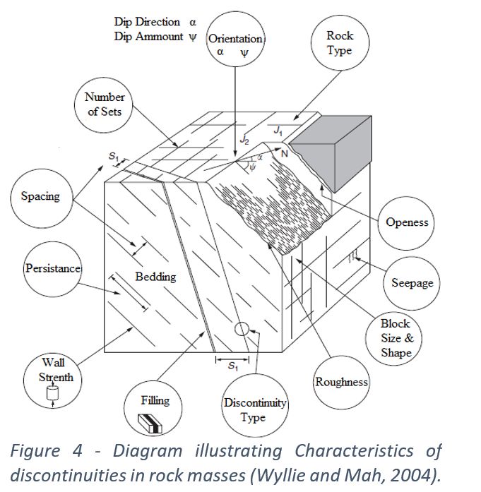
- Orientation – described in dip and dip
- Number of discontinuities set
- Spacing
- Persistence
- Roughness
- Wall strength
- Aperture (Openness)
- Filling
- Seepage
- Block size
Several approaches were done to seek how to correlate properties rock mass results with the fragmentation distribution. Based on that, it was defined the “Blastability Index” or BI. Due to the ease application, the BI proposed by Lilly (1986) became crucial and widely applied in fragmentation prediction models. Lilly´s parameter underwent changes to improve the quantification of the rock factor of the Kuz-Ram model described in (Cunningham, 1983, 1987). Subsequently the equation proposed by Cunningham (1987) to calculate the rock factor (A) comes from the adaptation of the BI proposed by Lilly in 1986:
A = 0,12 *BI
A = 0,06 (RDM +JF + RDI + HF)
It was reduced by Cunningham (2005) with the RDM incorporating the total weight of JF:
A = 0,06 (RDM + RDI +HF)
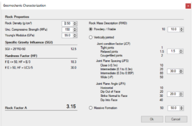
Where:
- RMD = Rock Mass Description
- JF = Joint factor
- RDI = Rock Density Index
- HF = Hardness Factor
In general, the geomechanical parameters mentioned above, were used to evaluate the rocks based on their integrity and structures and to obtain a scale factor named as rock factor that simplistically characterizes a multidimensional reality in relation to the difficulty to blast.